Types of IO for Embedded Devices
Types of IO for Embedded Devices
So, you're a mobile app developer stepping into the exciting world of embedded systems with a Raspberry Pi or an Nvidia Jetson Orin Nano. You're used to crafting slick user interfaces and managing data with APIs. But now you're faced with a new vocabulary: GPIO, I2C, SPI, and UART. What are they, and how do you even begin to use them?
You've probably seen these pins on your Raspberry Pi or Jetson Orin Nano shown here:
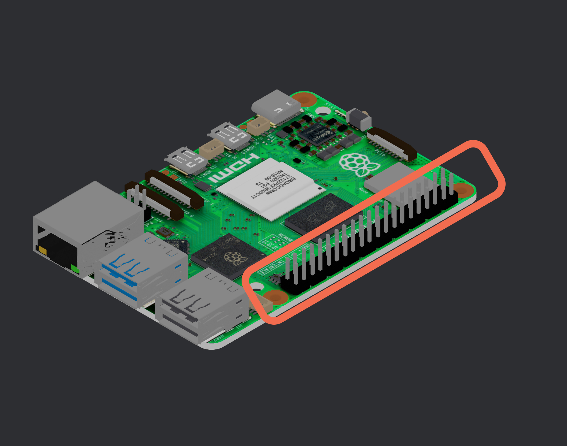
They are the essential communication lines that bring your software commands to life in the physical world. This guide will demystify these fundamental concepts and provide you with the practical knowledge to start building your own embedded projects. So if you want to build a robot, a drone, or a smart home device, communicating to sensors and actuators require a good understanding of these IO types.
⚠️ Critical Safety Warning
BE EXTREMELY CAREFUL when connecting devices to GPIO pins! Inserting the wrong voltage or connecting to the wrong pin can permanently damage or brick your device. Common mistakes that can destroy your board:
- Applying 5V to a 3.3V pin
- Shorting power pins to ground
- Connecting outputs to outputs (creating a short circuit)
- Drawing too much current from a single pin
- Incorrect polarity on power connections
Always double-check your connections before powering on!
Finding Your Pin Layout
On Raspberry Pi devices, you can run the following command in the terminal to see a detailed pinout diagram:
Raspberry Pi
pinoutThis will display an ASCII representation of your board's GPIO header with each pin clearly labeled, showing:
- Pin numbers (both physical and GPIO/BCM numbering)
- Power pins (3.3V, 5V, GND)
- Special purpose pins (I2C, SPI, UART)
For other devices like Nvidia Jetson, refer to the official documentation for accurate pinout diagrams. Never guess - always verify!
GPIO: Your Digital On/Off Switch
GPIO stands for General-Purpose Input/Output. These are the most basic and direct lines of communication with your embedded board. Think of them as simple light switches. You can programmatically turn them on (high voltage) or off (low voltage), or you can read their state (are they receiving a high or low voltage?).
Common Use Cases:
- Blinking an LED: The "Hello, World!" of embedded systems.
- Reading a button press: Detect when a physical button is pushed.
- Triggering a relay: Control high-power devices like lights or motors.
- Creating a simple alarm: Sound a buzzer when a sensor is triggered.
I²C: The Busy Middleman
I2C (Inter-Integrated Circuit), pronounced "I-squared-C," is a two-wire serial communication protocol. Imagine a small team where one person is the manager (the "master," your Raspberry Pi or Jetson) and can talk to multiple team members (the "slaves," your sensors or displays) using just two shared lines: one for data (SDA) and one for a clock signal to keep everything in sync (SCL). Each "slave" device has a unique address, so the master knows who it's talking to.
Common Use Cases:
- Reading from sensors: Many sensors for temperature, pressure, humidity, and light use I2C.
- Controlling OLED or LCD screens: Display text and simple graphics.
- Communicating with real-time clocks: Keep track of time even when your main board is off.
- Controlling motor drivers.
SPI: The High Speed Data Highway
SPI (Serial Peripheral Interface) is another serial communication protocol, but it's generally faster than I2C. It uses more wires, typically four: a clock line (SCLK), a line for data from the master to the slave (MOSI - Master Out, Slave In), a line for data from the slave to the master (MISO - Master In, Slave Out), and a chip select line (CS) for each slave device. This dedicated line for each slave allows for faster and more direct communication.
Common Use Cases:
- High-resolution displays: When you need to update a screen with a lot of data quickly.
- SD card readers: Transferring files to and from an SD card.
- Analog-to-Digital Converters (ADCs): Reading data from a wide range of analog sensors.
- Ethernet modules.
UART: The Serial Data Line
UART (Universal Asynchronous Receiver-Transmitter) is a simple, two-wire communication protocol. It consists of a transmit (TX) and a receive (RX) line. Data is sent as a stream of bits without a separate clock signal. Instead, both devices agree on a communication speed (the "baud rate") beforehand. This makes it great for simple devices that need to communicate over long distances or with low-bandwidth requirements.
Common Use Cases:
- GPS modules: Receiving location data.
- Serial consoles for debugging: A common way to access the command line of an embedded system.
- Connecting to other microcontrollers: For example, having your Raspberry Pi communicate with an Arduino or ESP32.
- Some RFID readers.
Comparison Table
| Feature | GPIO | I²C | SPI | UART |
|---|---|---|---|---|
| Wires | 1 per I/O | 2 (SDA, SCL) | 4 (or more) | 2 (TX, RX) |
| Speed | Low | Medium | High | Medium |
| Direction | Input/Output | Master/Slave | Master/Slave | Peer-to-Peer |
| Use Case | Control | Low-speed sensors | High-speed sensors | Serial comm |
| Addressing | Manual | Yes | Manual | No |
Stay Tuned
Hopefully this post has helped you understand the different types of IO for embedded devices. In the next post, we'll dive into how to use GPIO pins on your Raspberry Pi or Jetson Orin Nano with EdgeOS. In our next guide, we'll show you how you can use a DHT22 temperature and humidity sensor with EdgeOS using what we just learned.